
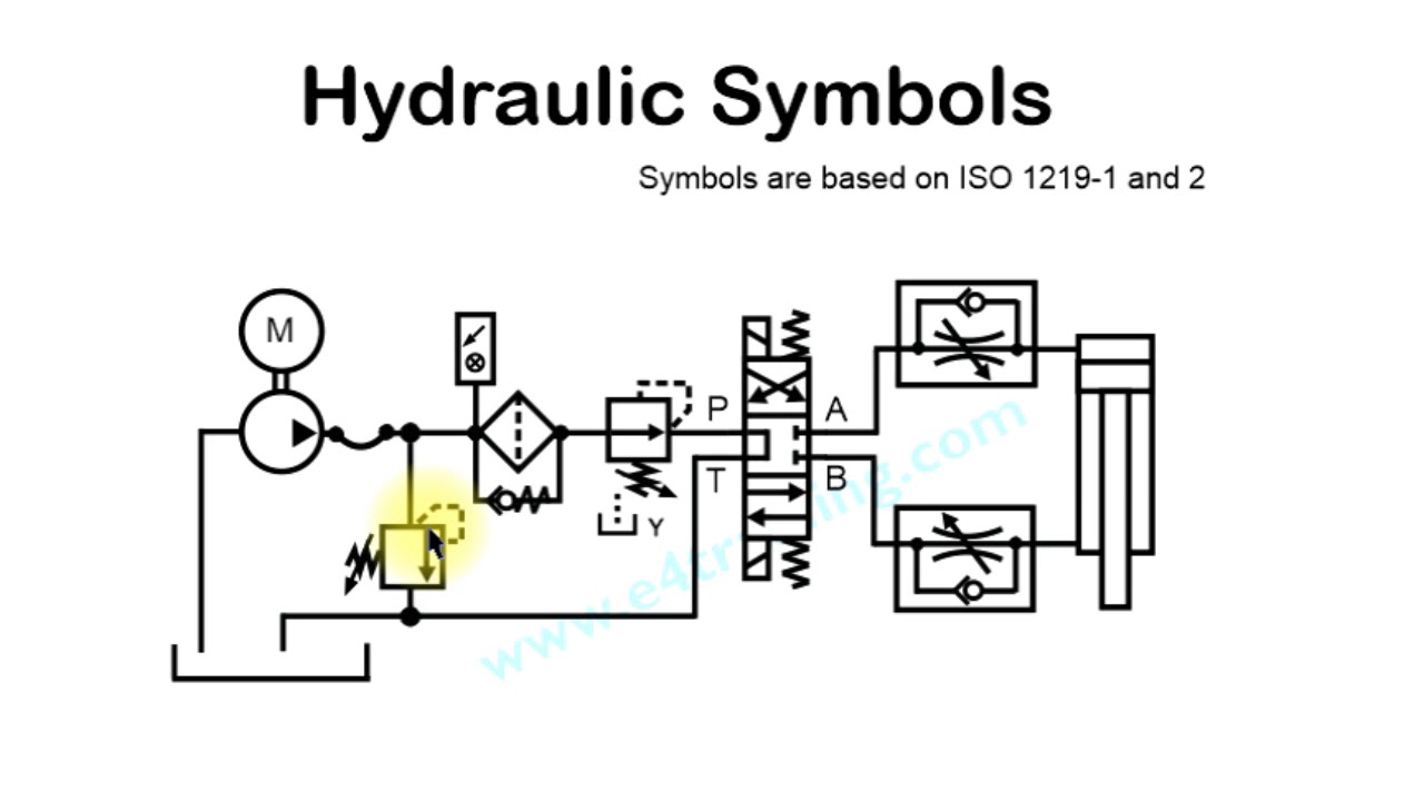
Hydraulic Circuit Symbols Explanation
Hydraulic Circuit Symbols Explanation, Indeed recently has been hunted by consumers around us, perhaps one of you personally. People now are accustomed to using the internet in gadgets to view video and image information for inspiration, and according to the name of this article I will discuss about
If the posting of this site is beneficial to our suport by spreading article posts of this site to social media marketing accounts which you have such as for example Facebook, Instagram and others or can also bookmark this blog page.

A Guide To Common Hydraulic Symbols Engineeringclicks Explanation For Employment Gap
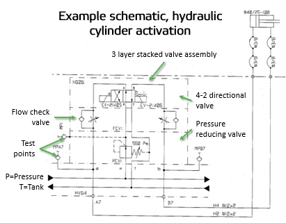
Reading Fluids Circuit Diagrams Hydraulic Circuit Examples Explanation For Employment Gap
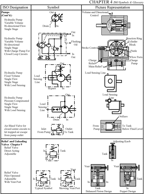
Chapter 4 Iso Symbols Hydraulics Pneumatics Explanation For Employment Gap
What S The Difference Between Hydraulic Circuit Symbols Machine Explanation For Employment Gap

Iso 1219 3 2016 En Fluid Power Systems And Components Explanation For Employment Gap
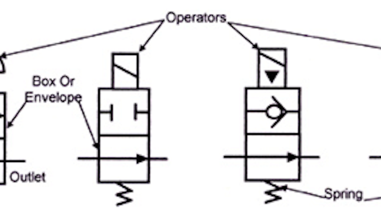
Book 2 Chapter 8 Directional Control Valves Hydraulics Explanation For Employment Gap


Hydraulic Cartridge Logic Valves Hydraulic Valve Explanation For Employment Gap
Hydraulic Circuit Symbol Explanation Youtube Explanation For Employment Gap

Component Circuit Symbols Pneumatic Components And Wp032e65 Explanation For Employment Gap
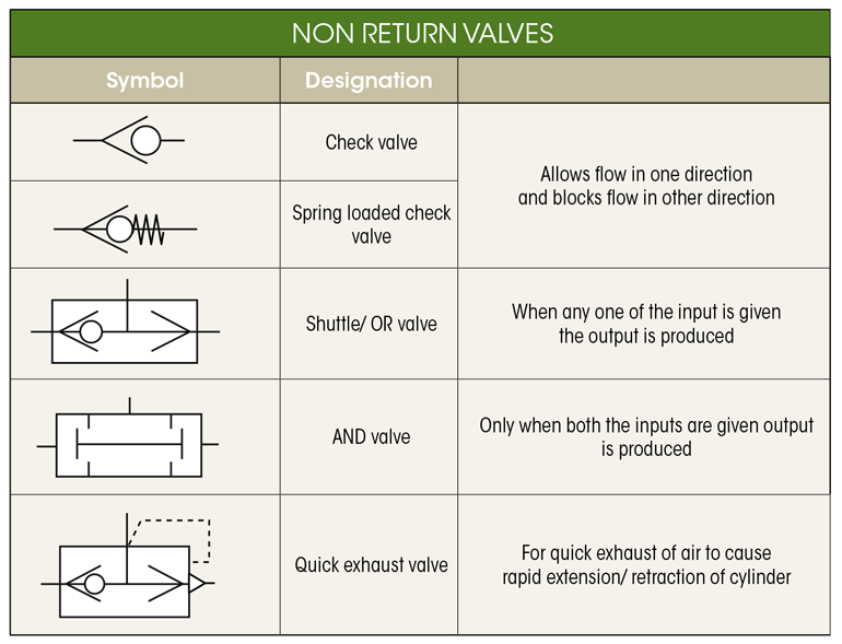
Hydraulic Pneumatic Circuit Symbols Roy Mech Explanation For Employment Gap